With the development of computer technology, information technology, control technology, and the continuous improvement of people's material living standards, traditional houses have obviously failed to meet people's needs, and smart homes have emerged. A true smart home sensor network can connect all items to the 3G Internet through RFID and other information sensing devices for intelligent identification and management. In addition to the functions of traditional home system sensor data acquisition, analysis and security alarm, and mobile phone SMS remote control of household appliances switch, the dynamic smart home system studied in this paper can obtain home information in real time by adding the mobile intelligent gateway. . Remote communication with the smart home system through SMS and Internet communication with the smart home gateway.
1 Dynamic smart home system based on Zynq platform
1.1 System Research Background <br>The current embedded design is developing rapidly, with high performance, low power consumption and high flexibility in scenarios involving a large number of data processing modules (such as intelligent video surveillance, advanced industrial control, etc.). The demand for processors is high, the existing microprocessor lacks sufficient signal processing capability, and the Zynq-7000 is a high-performance and low-power processor platform with an ARM+FPGA architecture that provides flexibility and flexibility. Extended solution.
The traditional smart home system main control CPU generally adopts ARM+Zigbee solution. In this system, Zedboard FPGA (field programmable logic gate array) is used as the main control CPU, Zigbee module adopts CC2530 Soc solution, GPRS module adopts sim300. The module uses the AT command to interact with the user's mobile phone, and the Internet interaction is implemented by BOA and CGI. The FPGA implements a PWM signal to generate a logic controlled motor.
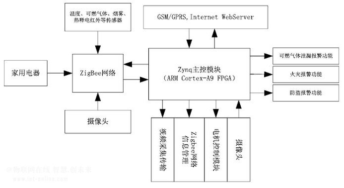
1.2 System Implementation Architecture <br> As shown in Figure 1 below, the functions completed by the main control module mainly include the Zigbee Coordinator, GSM/GPRS, Internet interconnection, camera video acquisition and motor drive car control. The module contains two processes, the process one is responsible for taking Zigbee network data, and distributing the processed data to the GSM/GPRS module and the Internet WebServer module.

Figure 1 system hardware structure framework
The process one then includes three separate threads that interact with each module. The flow is as follows: pthread_t tid[3]; //Create thread number pthread_attr_t attr[3]; // allocate space for thread pthread_attr_init(&attr[0]); pthread_attr_setscope(&attr[0], PTHREAD_SCOPE_SYSTEM); . . . . . . / / Thread space initialization pthread_create (&tid[0], &attr[0], thread_serial_ttyPS1, NULL); / / create thread 1: for ZedBoard to obtain ZigBee network data pthread_create (&tid[1], &attr[1], thread_serial_uartlite_debug, NULL ); / / create thread 2: used for ZedBoard to send data packets to GSM pthread_create (&tid [2], & attr [2], thread_serial_ttyPS1toWeb, NULL); / / create thread 3: used for ZedBoard to send packets to the Internet pthread_join (tid [0], NULL);. . . . . . . / / In the main function, add the thread pthread_rwlock_destroy (&GPacketBuf_rwmutex); / / release the thread
The second process is the CGI module, which is called by the WebServer. Its functions include parsing the data packet and presenting the ZigBee information to the user in the form of a web page. The process is as follows: The first step is to create a data packet format. The second step is to use the HTML language to inform the user of the temperature sensor, battery power supply voltage, fire warning, burglar alarm, fan, and light switch status collected from the Zigbee ad hoc network through the web page. Users can view the complete information of the home situation by logging in to the Internet at the far end. The exact format of the packet will be given at the later ZigBee module.
2 ZigBee ad hoc network
2.1 ZigBee network node configuration <br> There are three kinds of devices in the ZigBee network: Coordinator: responsible for starting the entire network, it is also the first device of the network. The main function of the router is to allow other devices to join the network and assist itself in communicating as a terminal device. The terminal device has no specific responsibility for maintaining the network structure, it can sleep or be woken up.
As a mobile multi-purpose platform, tablet computers also provide many possibilities for mobile teaching. The touch-based learning & entertainment teaching platform allows children to efficiently improve their academic performance in a relaxed and pleasant atmosphere. Such tablet computers generally integrate two learning sections of various courses and systematic learning functions. Generally, it includes multi-disciplinary high-quality teaching resources. The education tablet has the following main functions: it has the functions of touch screen input, text editing, picture editing, data storage, data management, wired and wireless Internet access that ordinary tablet computers have; Management functions, search methods support manual search, query by keyword, query by time; text and pictures can be scanned and converted into documents to save.
Education Tablet,learning tablet,leaning machine,New learning tablet
Jingjiang Gisen Technology Co.,Ltd , https://www.gisengroup.com