Abstract: The working principle, composition and implementation method of a network wireless communication system composed of direct-spread MODEM, GPS, communication controller and DTE terminal are proposed. The hardware block diagram and software flow chart of the system are given, and a kind of it is introduced. typical application.
GPS (Global Positioning System) was established by the US Department of Defense for military purposes. It can provide land, sea and air navigation and positioning. It can provide two services. One is Precision Positioning Service (PPS), which uses P code; the other is standard positioning ( SPS), using C / A code. At the same time, GPS can also provide accurate second pulse signals, combined with the clock information in GPS data, to achieve the required system time slot synchronization.
The system proposed in this article is based on this characteristic of GPS,  Utilize direct-spread MODEM and communication controller to provide wireless data communication function for DTE terminal. The system sets different working time slots for each workstation, and under the coordination of GPS timing information, it completes the data transmission / reception between each workstation in the system. As a network wireless system, this system can be widely used in military, transportation, and commercial fields.
1 System composition and working principle
The system consists of several workstations. According to the number of workstations, the length of the cycle is divided; within a cycle, it is divided into several time slots, each workstation is assigned a transmission time slot. In this system, the period is 1s, each time slot is 50ms, and each workstation uses GPS seconds pulses and data information to complete the data transmission according to the system-set time slot. When a workstation sends, the remaining workstations are in the receiving state, the system composition is shown in Figure 1.
Each workstation includes: direct-spread MODEM, communication controller, GPS receiver and DTE terminal. The direct-spread MODEM works in half-duplex mode, and the popular controller controls its transmission / reception conversion. The maximum working rate can reach 76.8kbps. The system uses 9.6kbps. The data format is 1 start bit, 8 data bits, Stop bits, no parity bit. The communication controller is responsible for the control of the entire system. It completes three aspects of work: one is to receive the GPS second pulse signal and GPS time information to provide time slot timing for the system; the second is to exchange data with the DTE terminal; and finally Realize data exchange with direct expansion modem. The GPS receiver provides second pulse signals and GPS time information for communication control. The DTE terminal forms the information to be sent and receives information from other workstations sent by the communication controller. The wireless direct-spread MODEM is a transceiver of the workstation, and its transceiver status is managed by the communication controller.  The composition block diagram of the workstation is shown in Figure 2.
The data volume sent by each workstation in this system is 40 bytes, and the MODEM rate is 9.6kbps. Considering the transmission and reception conversion time of MODEM and the protection time of each time slot, the size of each time slot is set at 50ms, a cycle is defined as 1s, and the system capacity is 20 workstations. Each workstation in the system uses the same PN code, and each workstation is preset with a transmission time slot. When the working time slot of the system is the same as the preset time slot of the workstation, the workstation is in the sending state; while in other time slots, the workstation is always in the receiving state, receiving information sent by other workstations.
2 Workstation hardware design and implementation
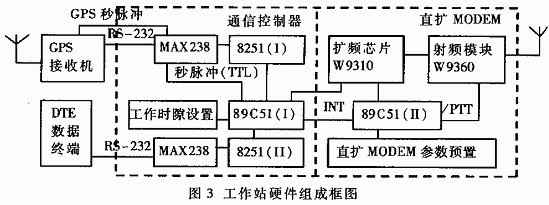
The workstation is composed of four parts: direct expansion MODEM, communication controller, GPS receiver and DTE terminal. Figure 3 is its circuit connection diagram.
GPS receiver and DTE data terminal and communication controller adopt RS-232 interface, communication controller uses 2 8251. Among them, 8251 (I) sends the received GPS information to the MCU 89C51 (I), 89C51 (I) sends the data of the DTE terminal to the direct expansion modem through its own serial port, and 8251 (II) receives the other received by the direct expansion MDOEM Workstation data and send it to the DTE terminal of this workstation. The working time slot setting in the communication controller specifies the sending time slot of the workstation. Two MAX238s realize the RS-232 and TTL level conversion. Among them, the second pulse provides a time slot interrupt for 89C51 (I). When the system time sends a time slot for this workstation, 89C51 (I) generates an interrupt INT to 89C51 (II ), 89C51 (II) output / PTT effective signal, so that the RF module completes the transmission / reception conversion.
The direct-spread MODEM is mainly composed of the spread-spectrum chip W9310, the RF module W9360, the MCU 89C51 (II), and the parameter preset of the direct-spread MODEM. The code length of the spread spectrum chip is 32 bits, PN is set by the MCU, and it can work in full-duplex or half-duplex mode. Its transmission power is divided into two levels, high and low. If the desired transmission distance is not achieved, an external power amplifier can be connected; the direct expansion MODEM can be flexibly set according to the system's operating distance, transmission rate and working mode. In addition to expanding the working status of MODEM, it also receives the INT interrupt signal sent and received from the 89C51 (I) in the communication controller, so that the RF module completes the transmission / reception conversion and establishes the communication link.
The data received and sent in the system are provided by the DTE terminal.
In addition to time information, GPS data also includes other information such as longitude, correction and speed. Here, only its time information is read, combined with the GPS second pulse to realize the time slot timing of the system. The data format of GPS is as follows:
| STX | id | dddd | it | id | dddd | it | ... | id | dddd | it | ETX |
Among them, STX: STX characters in ASCII
id: data item identification (single character)
dddd: data item content
it: data item structure ((CR) or (CR) (LF))
ETX: ETX character in ASCII
3 Workstation software design and implementation
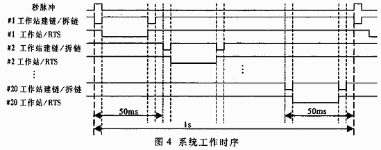
According to the working principle of the system, each workstation must complete the link establishment, RTS request transmission and data transmission in the sending time slot, and receive the information sent by other workstations in other time slots. The system timing is shown in Figure 4. 
The second pulse repetition period is 1 second, and the sending time of each workstation is 50ms. In the transmission time slot of each workstation, the workstation first generates a negative pulse for the link building / unlinking signal, so that the direct-spread MODEM changes from the receiving state to the transmitting state, and starts establishing links with other workstations. After the link is established, the communication controller sends the / RTS signal to inform the direct expansion modem, and the communication controller will then send the DTE data, which is sent to other workstations. At the end of the transmission time slot, the workstation has to complete two tasks, one is that / RTS changes from low to high, the communication controller stops the DTE of the workstation from sending data out, and the second is that the link building / unlinking signal generates a negative The pulse makes the DS modem disconnected, the sending task of the workstation ends, the DS modem changes from the sending state to the receiving state, and finally a little protection time is left. At this point, the sending work of the workstation is completed, and other workstations begin to repeat the sending sequence of the workstation until the 20 workstations in the system completely send it within 1 second. When the next second pulse arrives, the system repeats the sending sequence within the previous second, and each workstation sends in turn according to the set time slot number.
It can be seen from the working sequence of the system in FIG. 4 that the procedures of each workstation are divided into two parts: the software flow of the communication controller and the software flow of the direct expansion MODEM, and their tasks are different. 
The functions realized by the communication controller are:
· Receive GPS second pulse interruption and time information;
· Receive the information of other workstations received by the direct expansion modem;
· Send DTE the information of other workstations received by Direct Modem;
· Send the information that the workstation should send to other workstations to the direct expansion modem;
· Request the control information of chain building, chain breaking and data transmission from the direct expansion modem, that is, chain building / chain breaking signal, / RTS signal;
· Use GPS second pulse interrupt to realize system timing;
· Using the 89C51 (I) on-chip timer, the 89C51 (I) outputs / RTS, linking / unlinking control signals.
In addition to completing functions such as sequence addition and de-spreading, and RF signal transmission / reception, the DS MODEM only writes the functions that the communication controller requires it to implement due to space limitations, mainly including:
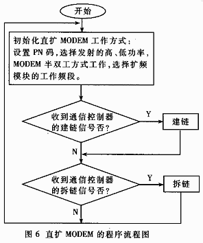
According to the link-building signal sent by the communication controller, the radio frequency module W9360 is controlled to complete the state transition from receiving to sending, and to establish a half-duplex link with other workstations. 
According to the / RTS signal sent by the communication controller, radiate the data sent by the communication controller.
According to the above functional description, the program flow charts of the communication controller and direct-spread MODEM are shown in Figure 5 and Figure 6, respectively.
In the program flow chart of the communication controller, the second pulse timing interrupts the starting point of the subprogram production system time reference, which starts the system timing. The timer interrupt subroutine generates an interrupt signal according to the sending time slot of the workstation. 89C51 (I) sends / transmits / RTS and establishes and delinks signals to the direct-spread MODEM to control the direct-spread MODEM to complete the reception and transmission state transition. The program first initializes 89C51 (I), 8251, opens the second pulse interrupt and timer interrupt, and then uses the query method to control the reception and transmission of data, including receiving GPS second pulse interrupt and time information, and receiving other workstations received by Direct Modem Information,  Send DTE the information of other workstations received by DS MODEM and send the information of the workstation to other workstations to DS MODEM.
In the program flow chart of the direct-spread MODEM, the direct-spread MODEM establishes a half-duplex link with other workstations according to the link building and link breaking signals sent by the communication controller, and realizes the conversion of the receiving and sending working status of the spread spectrum module, and completes data transmission.
4 A typical application of the system
Paratrooper rescue is a typical example of the application of this system.
When parachutists jump from the plane, due to the different time of parachuting and the change of wind speed and direction, they will be together within the range when they land. Each person wears such a workstation, before the plane takes off, the topographic map of the paratroopers landing area is stored in the DTE terminal of the workstation, and each paratrooper is assigned a working time slot. In this way, after they land, the workstation will automatically transmit the position of each paratrooper and the information they have collected to other paratroopers, providing a strong guarantee for them to successfully complete the mission.
In this paper, the network-based wireless communication system based on GPS has stable and reliable performance in practical applications, and it satisfies the use requirements well.
According to the actual use, the system can be improved in the following aspects:
· One cycle of this system is set at 1s. In actual use, you can use the second pulse and GPS time information to increase the time of a cycle; in addition, the length of the time slot sent by each workstation can also be set according to the amount of data and the size of the transmission rate.
SHAOXING COLORBEE PLASTIC CO.,LTD , https://www.fantaicolorbee.com