The anode dissipated power of the 300B tube is twice that of 2A3. Another characteristic of the 300B is that the anode voltage limit is higher, and the AB1 type push-pull can output more power. However, in general production, the output power of the 300B single-ended Class A power amplifier is only 7-8W, which is extremely difficult to reach 10W. One of the reasons is that the 300B single-ended Class A output supply voltage is usually selected to be about 400V, and the positive-positive-pressure linear region is naturally limited. Of course, the maximum output power is also limited by nonlinear distortion.
The 300B can output more power even at an anode voltage of 400V, but the nonlinear distortion is already quite large. According to the 300B single-ended Class A application parameters published by Xidian, when the anode voltage Ua=400V, gate negative voltage Ug=-84V, anode current 80mA, optimal load impedance ZL=2.5kΩ, the output power Po=12.5W The nonlinear distortion THD=5.5%, THD is slightly larger, contrary to the original intention of using 300B. According to the usual THD idiom scheme, it seems that the negative feedback can be reduced to less than 2% through the output stage, but the 300B power amplifier is not suitable for increasing the loop negative feedback or the output stage negative feedback.
Because the driving voltage of such a three-pole output tube has been extremely impressive, the negative feedback is added to increase the output voltage of the output stage, which increases the burden on the driver stage and causes the nonlinear distortion to rise sharply. Therefore, a Hi-Fi amplifier composed of a low internal resistance transistor generally does not add negative feedback under the condition that the output stage distortion is extremely small, and even if negative feedback is added to the pre-stage voltage amplification loop, the output stage is not included in the negative feedback. In the loop, and the negative feedback of the voltage amplification loop should not be too large, generally less than 10dB.
When the current stage uses a medium-low μ three-pole voltage amplifying tube, it has better characteristics even without negative feedback. In order to obtain an index of output power 12W and THD <1%, the following circuit combinations are used as shown in the figure.
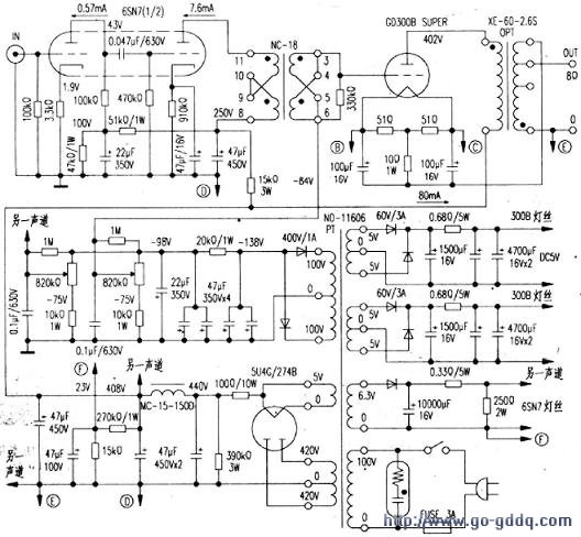
1. Adopt fixed gate negative pressure mode. The filament is powered by DC 5V, and the filament is connected in parallel with 51Ω×2 resistor, so that the midpoint of the filament is the common ground terminal, and the neutral point of the filament is composed of 51Ω×2 parallel value 25Ω, and the self-supplied gate negative voltage resistor composed of 10Ω resistor. In the zero-signal state, the filament has a voltage drop of 35Ω×0.08A=2.8V from point to ground, which forms part of the 300B gate negative voltage. The purpose of this resistor is to protect 300B, such as 300B anode current increases due to circuit failure. The pressure drop of the negative pressure portion of the self-supplied gate is increased, so that the increase of the anode current is suppressed, and the driving overload and load short circuit of the 300B are protected. In order to prevent the resistor from forming a negative current feedback and increase the internal resistance of 300B, a large-capacity bypass capacitor is connected across the resistor. In order to make the driver stage output distortion 10Vp-p drive voltage, the machine chose the boost input transformer coupling.
2. Design of voltage amplification stage
The driver stage uses 1/26SN7, and the drive transformer uses Japanese NC-18 (similar to the aforementioned NC-19, only the parameters are different).
The characteristics of NC-18 are as follows:
Primary-to-secondary voltage ratio (approximately equal to the turns ratio) (1+1): (1.5 + 1.5) (ie, two groups of 1:1.5).
The primary maximum bias current is ≤15mA when the two groups are connected in series, and ≤<30mA when the two groups are connected in parallel.
Frequency response characteristics, the primary uses the amplification tube internal resistance Ri = 8kΩ, the anode current = 10mA, the test with 4V input signal is 25Hz ~ 25kHz - 2dB.
The primary inductance, excitation current 10mA, is 80H with a 50Hz/5Vrms voltage test.
The secondary maximum output voltage, when the frequency is 35Hz, the drive tube Ri=8kΩ, and the anode current=10mA, the nonlinear distortion is 2% when the secondary output is 2×100Vrms.
Primary DC resistance 2 × 3000, secondary DC resistance 2 × 750Ω.
Between the primary and secondary, the primary and secondary pairs of iron core electrical strength DC1000V.
The 6SN7 anode voltage is 250V, the anode current is 7.6mA, and the gate negative voltage is -7V. The maximum voltage gain can be close to 30 times, that is, the input signal peak value is 4Vp-p, and the output signal can reach up to 120Vp-p. According to the above parameters of the coupling transformer NC-18, when the anode voltage is 250V, the positive half-cycle anode current can reach 18mA. When the signal is negative for half a week, the instantaneous value of the anode current can be reduced to nearly 1 mA, and the anode current with a variation range of 17 mA is sufficient to generate an output voltage of 136 Vp-p when the minimum impedance of the transformer primary is 8 kΩ, and then 1.5 times the voltage of the transformer. The maximum output calculated is 204Vp-p. In order to make the drive stage nonlinear distortion smaller, the anode current dynamic range of the driver stage is compressed to a variation rate of about 14 mA by lowering the input signal of the driver stage in the preamplifier. For this reason, the input signal of the driver stage is 3.5Vp- p can meet the requirements.
The preamplifier is composed of the other half of the 6SN7 before the driver stage to meet the output of 12.5W when the input sensitivity is 600mV.
3. Design of the power supply system
In order to achieve low noise amplification, the tube filaments are all powered by DC, with CRC filtering composed of two large capacitors.
The 5W0.68Ω filter resistor can also be used to precisely adjust the filament voltage. The anode power supply adopts 5U4 full-wave rectification and choke coil filtering. The low internal resistance of the triode is sensitive to the anode power supply ripple. It is necessary to use the choke filter. When using 5U4, 274B for π-type filtering, limited to its maximum peak current, the input filter is limited to a capacitor with a dry 4μF. The machine uses a 47μ capacitor series 1000 current-limiting resistor to limit the peak value of the charging current at the startup. The parallel 390kΩ resistor forms a voltage-divided bleeder circuit that allows the input filter capacitor charging voltage to not exceed 450V when turned on.
In order to further reduce the noise, the resistor divider voltage output +23V from the rectified voltage 408V is applied to the filament circuit of the preamplifier tube 6SN7, so that the 6SN7 cathode has a potential difference of -23V to the filament to avoid the thermal electron emission of the filament. Cathode absorption introduces additional ac noise.
The output stage is powered by a fixed gate negative voltage, rectified by a crystal diode, and CRCπ-type filtering is formed by resistors and capacitors to prevent the gate negative voltage ripple from entering the gate of 300B to form severe AC noise. Class A amplifier gate negative voltage supply has no load current, so both the filter and the gate negative voltage regulator divider can use high value resistors to adjust the gate negative voltage through the 820KΩ potentiometer, so that the anode current is 80mA when the 300B is static. In the figure, the transformers are all finished products on the Japanese market, and can be replaced by products of the same specifications.
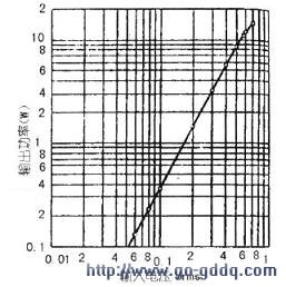
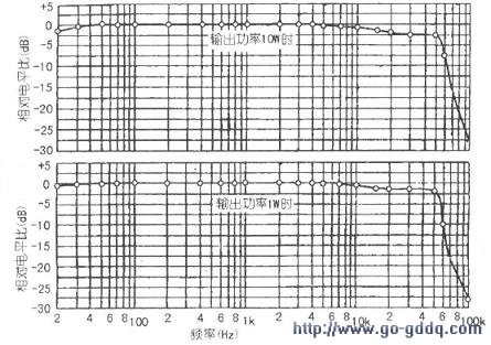
According to the input/output characteristics of the amplifier reported in the original test, the output power and the N+THD relationship are as shown in the middle figure. The output frequency is 10W and the frequency response characteristic is as shown in the right figure.

Disel and gas power plant with high volatge diesel generators, Gas Generator, power plant management system
·Engine and alternator shall be mounted on a same frame steel skid.
·Comply with ISO8528 national standard and ISO9001 quality standard.
. Voltage: 3kV, 3.3kV, 6kV, 6.3kV, 6.6kV, 10kV, 10.5kV, 11kV,13.8kV
·World famous brand High Voltage AC alternator: Stamford, Leroy Somer, Marathon, Faraday, etc
·Advanced and reliable controller: Auto start, AMF & Remote control by PC with RS232/485
·Full range protect function and alarm shutdown feature.
Power Plant,Gas Power Plant,Diesel Power Plant,Lighting Tower
Guangdong Superwatt Power Equipment Co., Ltd , https://www.swtgenset.com