Electric digital display low temperature compliance tester
ZSY-1 type
one,
Electric digital display low temperature compliance tester
Introduction:
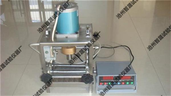
This instrument is designed and manufactured according to GB/T328.14-2007. The electric digital display low temperature compliance tester is used to determine the minimum temperature at which the bitumen waterproofing membrane is bent without bending under the specified conditions. It consists of a low temperature compliance test mechanical part and a control instrument part. Work in freezing fluid or air. It has the advantages of convenient use and high intelligence. It is an ideal new standard product for testing units, coil production units, universities and colleges. The series low temperature compliance tester adopts a number of international advanced technologies. The input adopts digital calibration and self-calibration technology. The measurement and control are accurate and stable, and the measurement error caused by temperature drift is eliminated. The instrument adopts multiple protection and isolation design, which has strong anti-interference performance and high reliability.
two,
Electric digital display low temperature compliance tester
The main technical parameters:
1. Test temperature range: -40 ° C ~ 70 ° C. Accuracy: Temperature: ±0.
3% FS
Time: 1-9999 minutes.
2. Bending rod diameter: 20.30.50mm
3, bending rod lifting speed: 360 ± 40mm / min
4, can place 6 test pieces
5, power: AV220V 50Hz
6, the size of the dimensions: 350 × 285 × 440mm
7, weight: 11Kg
three,
Electric digital display low temperature compliance tester
Installation and commissioning
1. Put the sink into the low temperature box and add the freezing liquid. Any mixture of frozen liquids:
- propylene glycol / aqueous solution (volume ratio 1:1) as low as -25 ° C, or
- an ethanol/water mixture below -20 ° C (2:1 by volume).
The liquid level is 100mm, and after the test piece has reached the specified temperature, it will remain at this temperature for 1h±5min.
2. Connect the host and controller lines, turn on the power supply 220V, and have reliable grounding. Turn on the power switch and adjust the bending axis position through the rising, falling, and stopping buttons on the control panel. Let the test piece be placed at the lowest end. The size of the test piece is (150±1) mm×(25±1)mm. Before starting all the tests, the distance between the two cylinders (see Figure 1) should be according to the test piece. Thickness adjustment, ie the diameter of the bending axis + 2 mm + the thickness of the test piece. The device was then placed in the cooled liquid and the upper end of the cylinder was about 10 mm below the surface of the frozen liquid, with the bending axis in the lower position.
It can be 20mm, 30mm, 50mm depending on the product.
3,
temperature setting
: Click the [Temperature Settings] button, the system will enter the temperature setting process (the temperature setting range is:
-50.0-+99.9
°C), at this time, the temperature display area digital tube will be at 2Hz frequency
Flashing
Display the last temperature setting result, click the [Add] button, the temperature setting value will rise at 0.1 °C resolution; press and hold the [Add] button, the temperature setting value will rise continuously; click the [Decrease] button The temperature set value will be reduced by 0.1 °C resolution; press and hold the [minus] button, the temperature set value will decrease continuously. After adjusting the temperature to the value you need, click the [OK] button and the temperature setting is completed.
4, temperature calibration
: Click the [Temperature Calibration] button and the system will enter the temperature calibration process (the temperature calibration range is:
-50.0-+99.9
°C),
At this time, the temperature display area digital tube will be at 4Hz frequency
Flashing
Display the actual value of the uncalibrated collected temperature, click the [plus] button, the temperature value will rise at a resolution of 0.1 °C; press and hold the [plus] button, the temperature value will continue to rise; click the [minus] button, the temperature The value will be reduced by 0.1 ° C resolution; press and hold the [minus] button, the temperature value will continue to decrease. After adjusting the temperature to the standard value you need, click the [OK] button and the temperature calibration is completed.
5, time setting
: Click the [Time Setting] button, the system will enter the sample test duration setting process (the sample test duration setting range is:
1-9999
minute
),
At this time, the time display area digital tube will be at 2Hz frequency
Flashing
Display the last time setting value, click the [plus] button, the number of minutes will increase by 1 minute resolution; press and hold the [plus] button, the number of minutes will continue to rise; click the [minus] button, the number of minutes will Reduced by 1 minute resolution; press and hold the [minus] button, the number of minutes will decrease continuously. will
Time setting
After adjusting to the setting value you need, click the [OK] button to complete the time setting operation.
6, lift time setting
: When the sample test is finished, the controller will automatically raise the test piece. The default process time of the rising process is 10S, then the lifting process will be automatically stopped. To change this setting, click the [lift time] button. The system will enter the lifting time setting process (the lifting time setting range is:
0-
200 seconds),
At this time, the time display area
The digital tube will have a frequency of 4Hz
Flashing
Display the number of seconds of the last lifting time, click the [plus] button,
Lift time
The value will rise in 1 second resolution; press and hold the [plus] button,
Lift time
The value will continue to rise; click the [minus] button,
Lift time
The value will be reduced by 1 second resolution; press and hold the [minus] button,
Lift time
The value will decrease continuously. After adjusting the number of seconds of the lifting time to the standard value you need, click the [OK] button, and the lifting time setting is completed.
7, start a test process
: Click the [Run Stop] button and the system will enter the sample test process.
,
At this point, the “Run†light flashes, indicating that the system is waiting for the current temperature value to reach the set value. When the temperature reaches the set value, the “Run†light is always on, indicating that the system officially enters the test process, and the time display area begins. Decrease the number of minutes remaining in the test sample. When the test process reaches the set test minutes, the system will automatically stop the test process and automatically raise the test piece; if the test needs to be terminated during the test, only Need to click again
[Run Stop] button.
8, lift up the test piece
: Click the [Up] button, the controller will lift the test piece upwards. If you need to stop the test piece, please click the [Stop] button.
9, down the test piece
: Click the [down] button, the controller will lower the test piece downwards. If you want to stop the falling test piece, please click the [Stop] button.
Sijee Fiber optic adaptors are part of passive components for FTTH ODN connectivity, Sijee Fiber optic adaptors are used to join two fiber optic patch cables together for realizing the transition between different interfaces and they are available for use with either single-mode or multimode fiber optic patch cord. Sijee Fiber optic adaptors can offer superior low loss performance with very high repeatability.
Sijee offers different types of fiber adaptors comply with ITU standard, main products including Fiber Mating Sleeve Adaptor, Fiber Hybrid Adaptor, Fiber Bare Fiber Adaptor, Fiber Mechanical Attenuator, Field Assembly Optical Connector (FAOC), Splice-On Connector, Semi-finished Fiber Connector, etc.
Optical Fiber Couplers,Optical Fiber Adapter,Fiber Optic Adapter,Fiber Optic Flange are available.
Features:
1. Compliant with: IEC, JIS, Telcordia
2. Convenience and ease of handling
3. Optical performance 100% factory tested
4. Flange or threaded mounting type
5. Ceramic/Zirconia or phosphorous bronze sleeves
6. Good changeability and repeatability
Applications:
1. Telecommunication networks
2. FTTX, FTTH
3. LAN, WAN, CATV networks
4. Fiber communications, Data communication networks and processing, Industrial, Mechanical and Military.
5. Active device termination


Optical Fiber Couplers,Optical Fiber Adapter,Fiber Optic Adapter,Fiber Optic Flange
Sijee Optical Communication Technology Co.,Ltd , https://www.sijee-optical.com