With the development of science and technology, intelligent control technology has begun to be widely used in the field of electronic testing. In modern industrial measurement and control systems, people often attach various sensors to the field bus to form a sensor network system. Various sensor devices are used as one of the network nodes, and between the node and the control center and between the nodes and the field through the field bus. Information transfer between nodes. Usually, people choose the CAN bus to connect most of the sensors. Therefore, the sensors need to be intelligent and unified. This paper designs a temperature and humidity digital sensor system with CAN communication interface based on C8051F060 microcontroller. The system can perform signal conditioning and analog-to-digital conversion on the pressure analog signal output from the pressure sensor; it can process and transmit temperature, humidity and pressure data. Establish a CAN bus sensor network to achieve data collection and communication.
Overall design of digital sensor systemAccording to the tasks and functions of the digital sensor system, the working principle of the system is shown in Figure 1. Firstly, the sensor collects the pressure signal, and performs the following filtering processing on the pressure signal, then collects the temperature and humidity data, and performs data frame processing and data communication. After the sensor is collected and preprocessed, the data is transmitted to the CAN bus through the CAN data communication interface according to the specified CAN application protocol. The data is collected and stored by the corresponding node, or directly transmitted to the host computer, and each node is monitored in real time by the host computer software. The data.
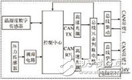
Figure 1 Digital sensor system working principle diagram
The digital sensor system is mainly composed of a control center module, a pressure acquisition module, a temperature and humidity acquisition module, a CAN bus module and a power module. The control center module selects C8051F060 single-chip microcomputer; in order to realize the data collection of temperature and humidity data, the data acquisition module selects SHT15, MPX4200A, TLV2402 and MAX291 devices; in order to complete the communication network, transmit data and realize bus redundancy, CAN bus module selects high-speed light Coupling, CD4052, TJA1050 and other devices.
Digital sensor system hardware designControl center module design
The control center module uses C8051F060 microcontroller, which is a fully integrated mixed-signal system-on-chip MCU introduced by Cygnal Corporation of the United States. The C8051F060 microcontroller uses the 8051-compatible patented core CIP-51 with speeds up to 25MIPS and features 59 digital I/O pins, five 16-bit general-purpose timers, and six programmable timers with capture/compare modules. Counter array. At the same time, the chip also integrates two 16-bit, 1Msps ADC and two 12-bit DACs, three voltage comparators, a watchdog timer, a VDD monitor and a temperature sensor. The chip integrates 64KB of FLASH and 4352B internal RAM, as well as hardware-implemented SPI, SMBus/I2C and two UART serial interfaces. The most important thing is that the C8051F060 MCU also integrates the CAN bus controller, which makes the C8051F060 MCU with CAN bus developed with strong anti-interference, low development cost and applicable to industrial field applications.
The working principle of the control center module is shown in Figure 2. The C8051F060 microcontroller is the core device of the control center module. It is mainly responsible for controlling the temperature and humidity data collected by the SHT15 and collecting and converting the pressure data after the following filtering, and then processing the data of these signals ( Filter processing, data frame, data buffer, etc.; meanwhile, because the C8051F060 microcontroller itself has a CAN communication interface, it can also achieve data transmission.
The specific circuit of the control center module designed according to Figure 2 is shown in Figure 3. Before the C8051F060 MCU is running normally, the application port and clock must be initialized. The port pins of the C8051F060 MCU can withstand the voltage value of 3V~5V, and the mode status of the P0~P3 pins can be configured according to requirements; in order to realize the system clock, This design uses an external crystal oscillator drive circuit to drive the external crystal.
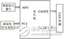
Figure 2 Control Center Module Working Principle Diagram
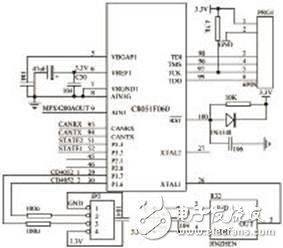
Figure 3 Control Center Module Circuit Diagram
Pcb Mounted Speaker ,Round Speaker With Pin,Min Pcb Mounted Speaker,Speaker For Voice Broadcast
Jiangsu Huawha Electronices Co.,Ltd , https://www.hnbuzzer.com