Design of high loudness speech circuit based on ISD1420
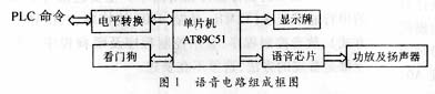
Introduce the design of a voice circuit, and explain the design principle and control method. This link uses the voice storage / regeneration chip ISD1420, BTL power amplifier circuit and speaker to form a high-power voice circuit, which is controlled by the microcontroller according to the command of the main control PLC.
Keywords: voice storage / regeneration chip; BTL circuit; single chip microcomputer?
 ?
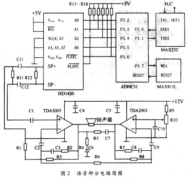
? The voice circuit design is shown in Figure 2. The "beep sound" and "starting gun sound" are stored in sections by the voice storage / regeneration chip ISD1420. The audio signal output by the ISD1420 is capacitively coupled to the BTL power amplifier circuit composed of two integrated power amplifiers TDA2003, and finally output by the speaker. MAX232 converts the RS? 232 level signal sent from PLC to TTL level and sends it to the single-chip AT89C51. AT89C51 controls the playback of ISD1420 through P3.6 according to the instructions of PLC, and P3.2 ~ P3.5 are used to adjust the playback Tone address. MAX813L is used as a watchdog to provide power-on reset and operation monitoring for the microcontroller AT89C51, and the dog feeding signal is provided by P3.7.
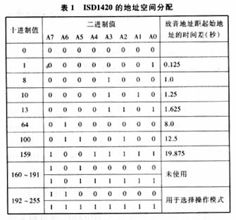
The address pins (A0 to A7) have two functions, depending on the state of A7 and A6. When one of A7 or A6 is "0", A0 ~ A7 are interpreted as address bits and used as the starting address of the current recording and playback operation. The circuit we designed uses the address bit function of A0 ~ A7. The address space allocation of ISD1420 is shown in Table 1. ?
AT89C51's P3.6 control, the playback time is determined by the P3.6 low-level hold time. The playback address is determined by P3.2 ~ P3.5. P3.5 = 0 is the address of “prompt toneâ€; P3.5 = 1 is the address of “starting gunshotâ€, and P3.2 ~ P3.4 are the address fine-tuning. The PLC issues commands when to play, which sound to play, and how long to play.
2.3 The starting device of the BTL power amplifier circuit requires that the battery can be used to supply power when there is no AC power supply, so the power supply is set to 12V. Since it is used outdoors, it requires that the sound emitted has a certain loudness, that is, the voice circuit is required to have a larger power output. The internal output stage of ISD1420 has an amplifier, and its direct speaker drive power is 12.2mW (16Ω load), which is very different from our actual needs, so the post-stage amplifier must ensure that it can output high-power signals at low voltage to promote The speaker sounds.
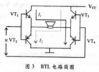
To output a high-power signal under a single-supply low-voltage condition, the power amplifier circuit selects a bridge-type transformerless output circuit (that is, a BTL circuit), and its basic working principle is illustrated by the discrete component BTL circuit diagram shown in FIG. 3. There are four output tubes VT1 ~ VT4 in the picture, and the speaker is connected between the two output ends. In the positive half of the input signal u, VT1 and VT4 are turned on, VT2 and VT3 are turned off, and the output current is shown as I1 in the figure. In the negative half of the input signal u, VT2 and VT3 are turned on, VT1 and VT4 are turned off, and the output current is shown as I2 in the figure. In the positive and negative half cycles, the potential difference on the speaker is in the opposite direction, and the magnitude is equal, both are close to the power supply voltage, so the utilization rate of the power supply is very high. The theoretical BTL circuit efficiency can reach 78.5%. ?
The actual circuit used is shown in Figure 2. Two 10W integrated power amplifiers TDA2003 are connected in the form of a BTL circuit, which is directly coupled to the speaker through a capacitor. Using the principle of "push" and "pull" at the same time, the peak-to-peak voltage of the sine wave on the speaker is approximately the power supply. Twice the voltage. The output can basically meet the requirements.
 ?
? Carbon Brush Motor is a rotary electric machine that includes a brush device that converts electrical energy into mechanical energy (electric motor) or converts mechanical energy into electrical energy (generator). Brushed motor is the basis of all motors. It has the characteristics of quick start, timely braking, smooth speed regulation in a wide range, and relatively simple control circuit.
Carbon Brush Motor
Carbon Brush Motor,Brushed DC Electric Motor,DC Brushed Motor,12V Brushed DC Motor,24V brushed DC Motor,Brush Type DC Motor
Shenzhen Maintex Intelligent Control Co., Ltd. , https://www.maintexmotor.com