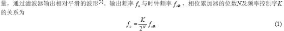
Direct digital synthesis (Direct Digital Synthesis, DDS) is a new type of frequency synthesis technology, which has the outstanding advantages of high frequency resolution and fast switching speed, and is widely used in arbitrary waveform generators.
The basic principle is shown in Figure 1. It is mainly composed of phase accumulator, waveform RAM, DAC and low-pass filter. The N-bit phase accumulator is added to the phase increment ϕΔ determined by the frequency control word K under the control of the sampling clock; the output of the phase accumulator (higher A bit) is used as the address of the waveform RAM to realize the conversion of the waveform phase to amplitude; Waveform data converted to analog by DAC
The use of DDS technology to generate an arbitrary signal requires updating the data in the waveform RAM [2]. However, the current commercialized DDS application-specific integrated circuits are almost all based on fixed sinusoidal signals, and there is no way to change the waveform data. Therefore, to achieve arbitrary waveform generation, you must design your own DDS. Due to the large scale of the DDS circuit, the use of programmable circuits (such as FPGA) to achieve is a reasonable choice [3, 4].
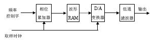
Figure 1 The use of DDS technology to generate an arbitrary signal phase accumulator is the core of DDS, how to ensure high accumulation acceleration is a key issue. The design goal of this paper is an arbitrary waveform generator with a sampling rate of 100 MSa / s, a memory depth of 64 K ∗ 12 bits, and a frequency resolution better than 100 μHz. It requires the phase accumulation rate of the main DDS to reach 100 MHz, and the accumulated number of bits is not less than 40 bits, which is difficult to achieve.
According to the basic principle of DDS, the frequency control word that determines the phase increment of the phase accumulator is used to change the output frequency of the waveform. The frequency modulation process of the waveform is the process of frequency change. Different modulation methods and signal frequency change laws are different. By changing the frequency control word of the DDS in real time, all kinds of frequency modulation of the waveform can be realized by the all-digital method. The key to the design is how to reflect the required modulation signal to the frequency control word in real time, that is, the waveform frequency modulation problem is finally reflected as the generation of the frequency control word.
The basic scheme of arbitrary wave generation and frequency modulation based on the above ideas is shown in Figure 2. It consists of two DDSs: the main DDS is used to generate an arbitrary signal that needs to be output, and the modulated DDS is used to generate a modulated signal (data). The modulation signal data is stored in the modulation RAM, which can be changed according to different modulation methods. For example, the modulation signal during linear frequency modulation is a sawtooth wave. The modulation signal data and the specified modulation parameters are properly calculated to generate the frequency control word of the main DDS to control the output frequency of the waveform in real time.
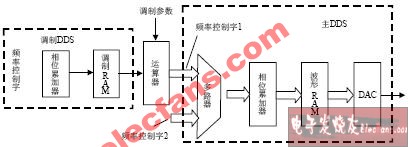
Figure 2 DDS-based arbitrary wave generation and frequency modulation scheme
Research on High Speed ​​Waveform Generation and Frequency Modulation Technology
USB 3.0 Hub
USB 3.0 Hub means the data buffering and throughput. They're the USB version of a regular plug extension lead, converting a single USB socket into a hub of them.Another characteristic of USB HUB 3.0 is that they contain more data buffering than USB 2.0 hubs.It store USB 3.0 SuperSpeed packets in a buffer and then retransmit them when there is an available time slot in the SuperSpeed data path.

USB 3.0 Hub,USB HUB M.2 SSD Enclosure,Solid State Drive Housing Case,Type-C to M.2 SSD Box
Pogo Technology International Ltd , https://www.pogomedical.com