introduction
Large-scale programmable logic devices CPLD and FPGA are the two most widely used types of programmable logic devices today. Electronic design engineers can use it to design the special chips and special products they need in the office or laboratory, thereby greatly shortening the product. Time to market reduces development costs. In addition, the programmable logic device also has the characteristics of static repeatable programming and dynamic reconfiguration in the system, so that the functions of the hardware can be modified by programming like software, which greatly improves the flexibility and versatility of electronic system design .
1 Working principle
MIDI music is a kind of synthetic music under Windows. Because it records a piece of music by notation, it can greatly reduce the storage capacity compared to wave music. The basic principle of MIDI music: the frequency value (tone) and the duration (tone length) of each note making up the music are two basic data that the music can play continuously, so as long as the frequency of the excitation signal output to the speaker is controlled High and low and the duration of each frequency signal can make the speaker emit continuous music.
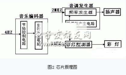
Figure 1 is a functional block diagram of the music player designed in this article. The music encoder stores the preset codes of four songs. By changing the state of the music selection switch, it is possible to decide which music is to be played. The music encoder controls the tone generator and the flashing light controller. Whenever the music rhythm clock sends a clock pulse to the music encoder, the music encoder sends the encoding of the currently played note to the tone generator and the lantern Flash the controller. The tone generator divides the 2MHz reference clock according to the frequency division coefficient corresponding to the code to obtain a pulse corresponding to the frequency of the current note to be played, and then uses this pulse to excite the speaker to obtain the sound of the note. The flashing controller of the colored lights sends the colored lights corresponding to the currently played note to the colored lights according to the code.

Among them, the three functions of tone generator, music encoder, and color light controller can be completed by ALTERA's programmable logic device (CPLD) EPF10LC84-4 chip, using VHDL language [1-3]. Audio amplifiers, colored lights, and various clocks can be realized by specific peripheral circuits.
2. Design of MIDI music generator chip
The key of this design is to accurately generate the frequency signal corresponding to each note in the music, and output it according to the beat according to the requirements of the music. In order to reduce the complexity of the system, this design changes the preset number of the counter regularly according to the requirements of the music according to the principle of the variable modulus counter, so that the frequency signal required by the music can be generated. The principle block diagram of the chip is shown in Figure 2. The chip is designed in the MUXPLUS II environment using VHDL hardware description language.
\ 
The beat control circuit in the figure generates the beat timing signal; the note generation circuit generates the notes required for the music according to the beat requirements; the pre-number generation circuit is controlled by the note, generates the preset number corresponding to the note frequency, and sends the counter to the data input end. The note frequency generator generates corresponding frequency signals according to different preset numbers, thereby completing the performance function of the music.
3 peripheral circuit design
3.1 Music rhythm clock and colorful lights flashing rhythm clock generation circuit
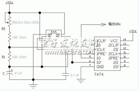
The music rhythm clock we need is a clock pulse of about 4Hz, and its frequency is very low, which can be generated by using a multivibrator composed of a 555 Timer, as shown in Figure 3.
The 555 integrated timer is a hybrid integrated circuit that cleverly combines analog functions and logic functions. The multivibrator circuit diagram formed by the 555 timer is shown in Figure 3, and the calculation formula of the pulse frequency output by pin 3 is:
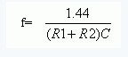
Changing the resistance of the variable resistor can change the output frequency. We require the output frequency to be 4Hz and C = 47Uf, so R1 + R2 should be 7.66K.
The music rhythm clock is very important to the entire music player. It is required that the music rhythm clock pulse is very stable, so as to ensure the smooth playback of music, otherwise it will be a messy sound, not music but noise. In order to make the output pulse more stable and reduce external interference, the output pulse is sent to the CPLD chip after the D flip-flop (7474), so the pulse frequency output by the 555 timer pin should be doubled (ie 8Hz), so R1 The resistance of + R2 should be 3.83K.
The flashing rhythm clock generating circuit of the colored lights has the same principle as the music rhythm clock generating circuit, and is also realized by a multivibrator composed of 555 timers, but the frequency of the colored lights controlling clock generating circuit is higher than that of the music rhythm clock generating circuit. In the range of dozens to tens of hertz, its R2 value is indefinite, and it can be determined according to its own requirements. If you want the color lights to flash faster, the frequency will be higher, and if you want to blink slowly, the frequency will be lower.
24 hours mechanical timer
Instant indicator
Min.setting time:15 minutes. Max.setting timer:24 hours
With hand switch,can be switched to operating and
setting at any time
Instructions:

1. Set program: 1 pin is equivalent to 15 minutes. Determine desired start time and push down pins until desired
off time.
For instance, if you want electrical devices to work from 8:00am to 11:00am and from 13:00pm to 17:00pm, you
just need to put down allthe pins between the three period time.
2. Set the current time: Turning the dial clockwise until the arrow pointing to
current time.
For example,if now it is 8:00 am, please turn the dial and make sure the
arrow point to 8. (See the picture.)
3. Plug the electrical device directly into the timer. Make sure the electrical
device is power-on.
4. Plug the timer into electrical outlet and the electrical device will be work
according to the setting program.
Note: = Normal Ope n = Timing
Make sure the switch on the Timing position. If it
is on the [Normal Open" mode, the electrical device is
always power-on and the timer function no work.
Specifications:
|
Rated Voltage, Current and Power |
As shown on the label |
|
Time Setting Range |
15minutes24hours |
|
Working Temperature |
-10℃?+55℃ |
|
Operation |
Clockwise |
|
Insulation Resistance |
>100M |
|
Inherent Loss |
≤1W |
Application:
1. To enable high-power electric appliances to run automatically at off-peak time if there is different electricity
price according to different periods of time in some areas.
2. To use for electric appliances which need time control, such as water heaters, air conditioners, drinking
fountains, rice cookers, advertising lights and so on.
3. To control the charging time. For example, battery of electric bikes or mobile phones, storage batteries, etc.
4. Occasions which need switch on/off frequently, like interval spray irrigation for flowersand lawn, cyclical
adding oxygen to fish jar, fountains and so on.
5. Home safety precautions and lighting.
Caution:
1.D o not exceed the maximum ratings of the timer.
2.M ust reset the current time after power failure.
3.D o not plug the timer directly into the working electrical appliances.
4.U nless changing the setting, keep the program same every day.
5.D o not disassemble timer by yourself. Professionals service are needed for maintenance.
6.T his item is only for indoor use.
Mechanical Timer, mechanical timer socket, 24hr mechanical timer, mechanical timer plug, mechanical timer adaptor
NINGBO COWELL ELECTRONICS & TECHNOLOGY CO., LTD , https://www.cowellsocket.com